
PRODUCT SYSTEMS / SELECT BY CONNECTION TASK

Six product families. One coordinated connection path.

NP83 dry-break interlock leads a portfolio of hoses, clamps, quick disconnects and sanitary components. Start with the service point, then define the operating conditions and mating interface.

FIND YOUR CONNECTION

Begin with the task, not a part number.

Keep the system in view while reviewing each component’s configuration limits.

6 product families

Dry-Break Interlock Valve

NP83

Dry-Break Interlock Valve

A controlled sequence for coupling, opening, closing and disconnecting.

View reference specifications
Selection itemReference configuration
Working pressure16 bar / 232 psi
Reference sizesNPS 1, 2, 3
Temperature range−20 to +80 °C / −4 to +176 °F

Approved drawings and the order configuration define final materials, interfaces and operating limits.
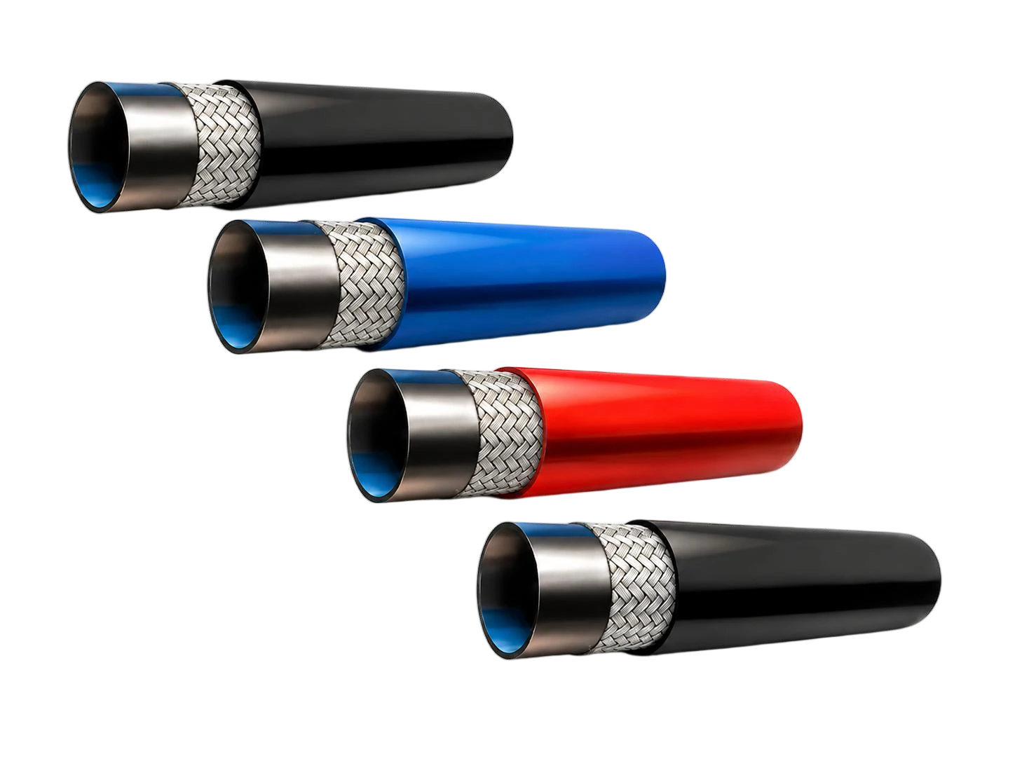
EPDM Liquid Cooling Hose

NLH · EPDM

EPDM Liquid Cooling Hose

Flexible coolant routing, specified around the fluid, bend space and end assembly.

View reference specifications
Selection itemReference configuration
Reference ID1/4–1 in + 2 in
Temperature range−40 to +100 °C
Working pressure reference150 psi; 1 in: 100 psi

Approved drawings and the order configuration define final materials, interfaces and operating limits.
Stainless Steel Safety Clamps

NPRK · STAINLESS

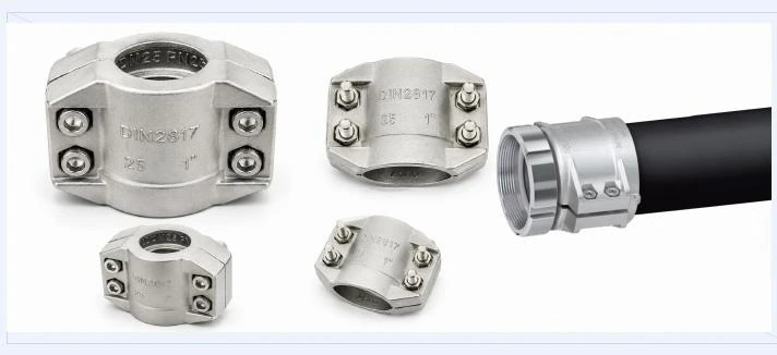
Stainless Steel Safety Clamps

Select by measured hose OD and review the hose, clamp and fitting as an assembly.

View reference specifications
Selection itemReference configuration
Reference rangeND 15–100
Body material options304 / 316 stainless steel
HardwareA2; M6 / M8 / M10

Approved drawings and the order configuration define final materials, interfaces and operating limits.
Liquid Cooling Quick Disconnects

UQD / UQDB

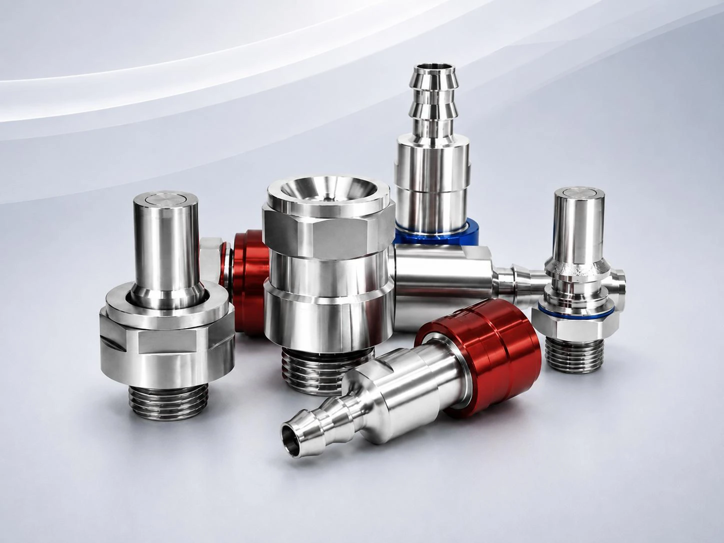
Liquid Cooling Quick Disconnects

Push-to-connect interfaces for rack and equipment service, reviewed by size and duty.

View reference specifications
Selection itemReference configuration
Typical pressure reference6.9 bar / 100 psi
Temperature range5–65 °C
End optionsORB / BSPP / Hose

Approved drawings and the order configuration define final materials, interfaces and operating limits.
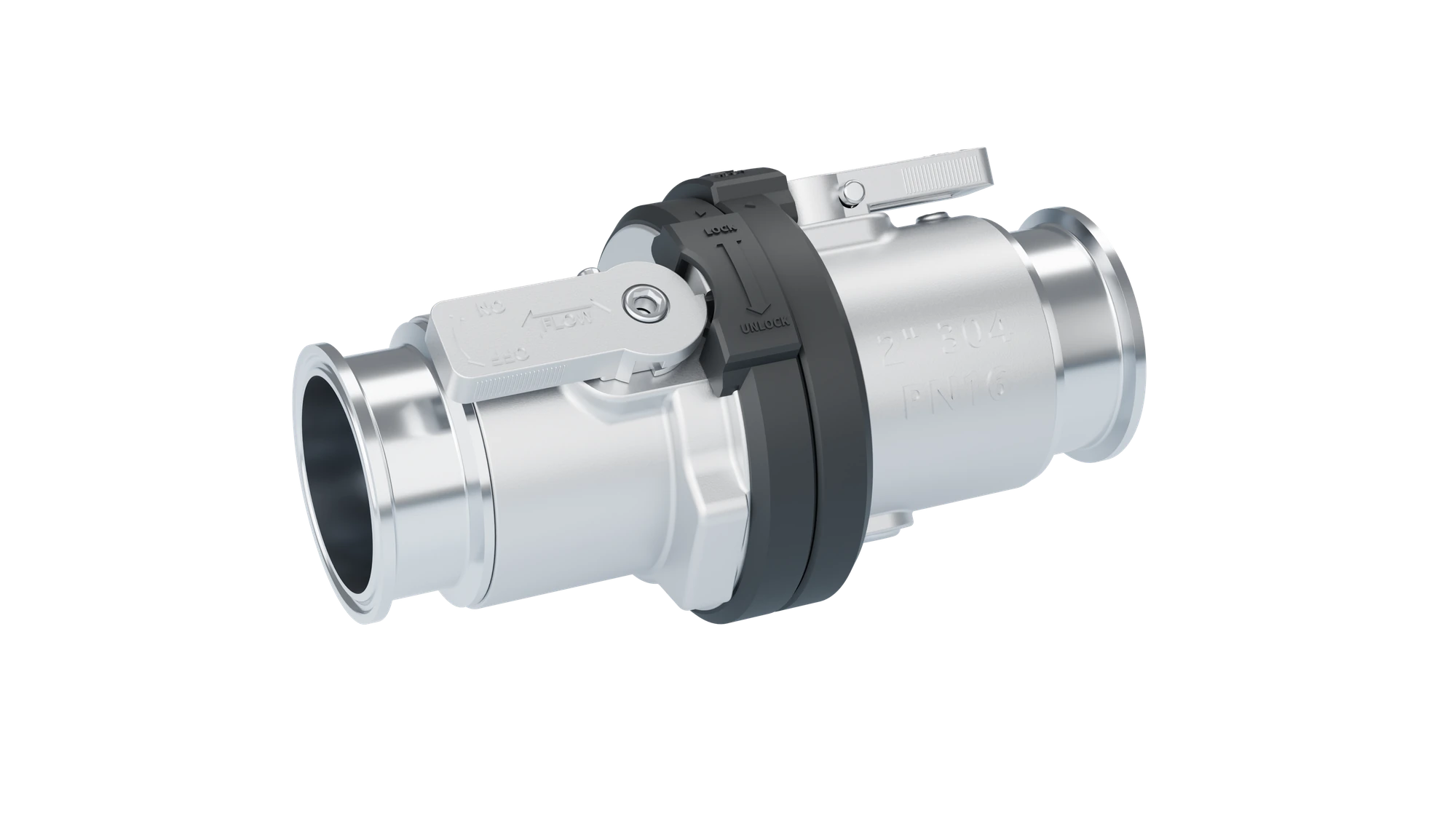
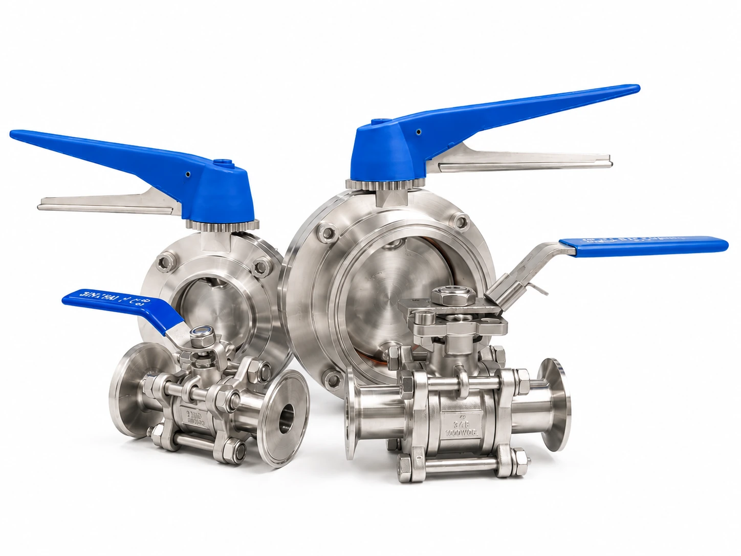
Sanitary Butterfly & Ball Valves

SANITARY VALVES

Sanitary Butterfly & Ball Valves

Sanitary isolation with multiple end connections and actuation configurations.

View reference specifications
Selection itemReference configuration
Working pressure reference16 bar
Temperature reference−20 to +80 °C
End configurationsClamp / Weld / Thread

Approved drawings and the order configuration define final materials, interfaces and operating limits.

Sanitary Fittings & Custom Interfaces

SANITARY FITTINGS

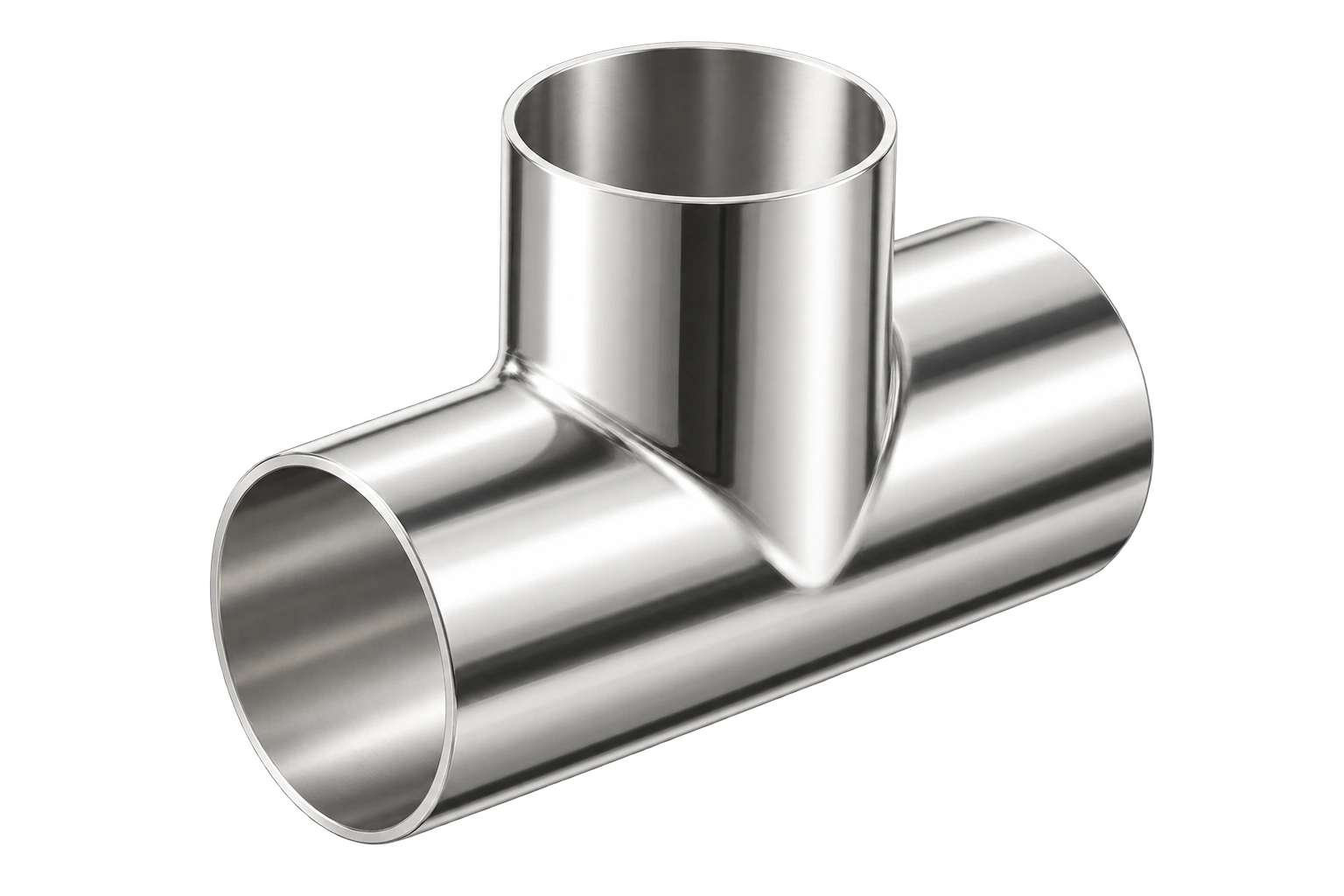
Sanitary Fittings & Custom Interfaces

Elbows, tees, reducers and adapters that connect standard components to real systems.

View reference specifications
Selection itemReference configuration
ComponentsElbows / Tees / Reducers / Adapters
Drawing reference families3A / BPE / ISO / DIN / MS
Customization basisMating drawing + operating conditions

Approved drawings and the order configuration define final materials, interfaces and operating limits.

REFERENCE SELECTION DATA

Readable data for the next engineering decision.

Reference hose and clamp dimensions for initial assembly selection. Confirm the actual duty and mating dimensions.

EPDM hose selection table
ModelIDODMin. bend radiusReference pressureReel pack
NLH-EP-04-BLK-RL1/4 in0.48 in1.0 in150 psi600 ft
NLH-EP-06-BLK-RL3/8 in0.63 in1.5 in150 psi450 ft
NLH-EP-06X-BLK-RL3/8 in0.60 in1.6 in150 psi450 ft
NLH-EP-08-BLK-RL1/2 in0.78 in2.8 in150 psi300 ft
NLH-EP-10-BLK-RL5/8 in0.91 in3.5 in150 psi250 ft
NLH-EP-12-BLK-RL3/4 in1.03 in4.5 in150 psi200 ft
NLH-EP-16-BLK-RL1 in1.28 in6.5 in100 psi150 ft
NLH-EP-32-BLK-RL2 in / 50.8 mm2.36 in / 60 mm10 in / 250 mm150 psi / 10.3 bar100 ft Reel

NLH-EP-16: 100 psi / 6.9 bar reference; other listed sizes: 150 psi / 10.3 bar. Review temperature, coolant and end components together.

NPRK safety clamp selection table
NDHose (mm)OD range (mm)H / W (mm)ThreadReference
1513 × 522-2450 / 51M6NPRK-013
2019 × 630-3350 / 63M6NPRK-019
2525 × 636-3950 / 69M6NPRK-025
3232 × 643-4650 / 76M6NPRK-032
4038 × 6.550-5250 / 83M6NPRK-038
5050 × 864-6756 / 102M8NPRK-050
6563 × 878-8274 / 120M8NPRK-063
8075 × 889-9376 / 132M8NPRK-075
100100 × 8114-119120 / 166M10NPRK-100

ND identifies the reference size; select by measured hose OD; confirm body material, A2 hardware and fitting geometry for the configuration.

REVIEW THE ASSEMBLY

The assembly defines the connection envelope.

Valve, hose, clamp, seal and mating end work as one configuration. Share the drawing, coolant, temperature, pressure and service requirements to establish a clear selection basis.