
CONNECTION ENGINEERING FOR LIQUID COOLING
Control the flow.
Own the disconnect.
Built around the NP83 dry-break interlock valve. A system-level approach to isolation, connection and service.
FROM PRECISION CASTING TO CONNECTION ASSEMBLIES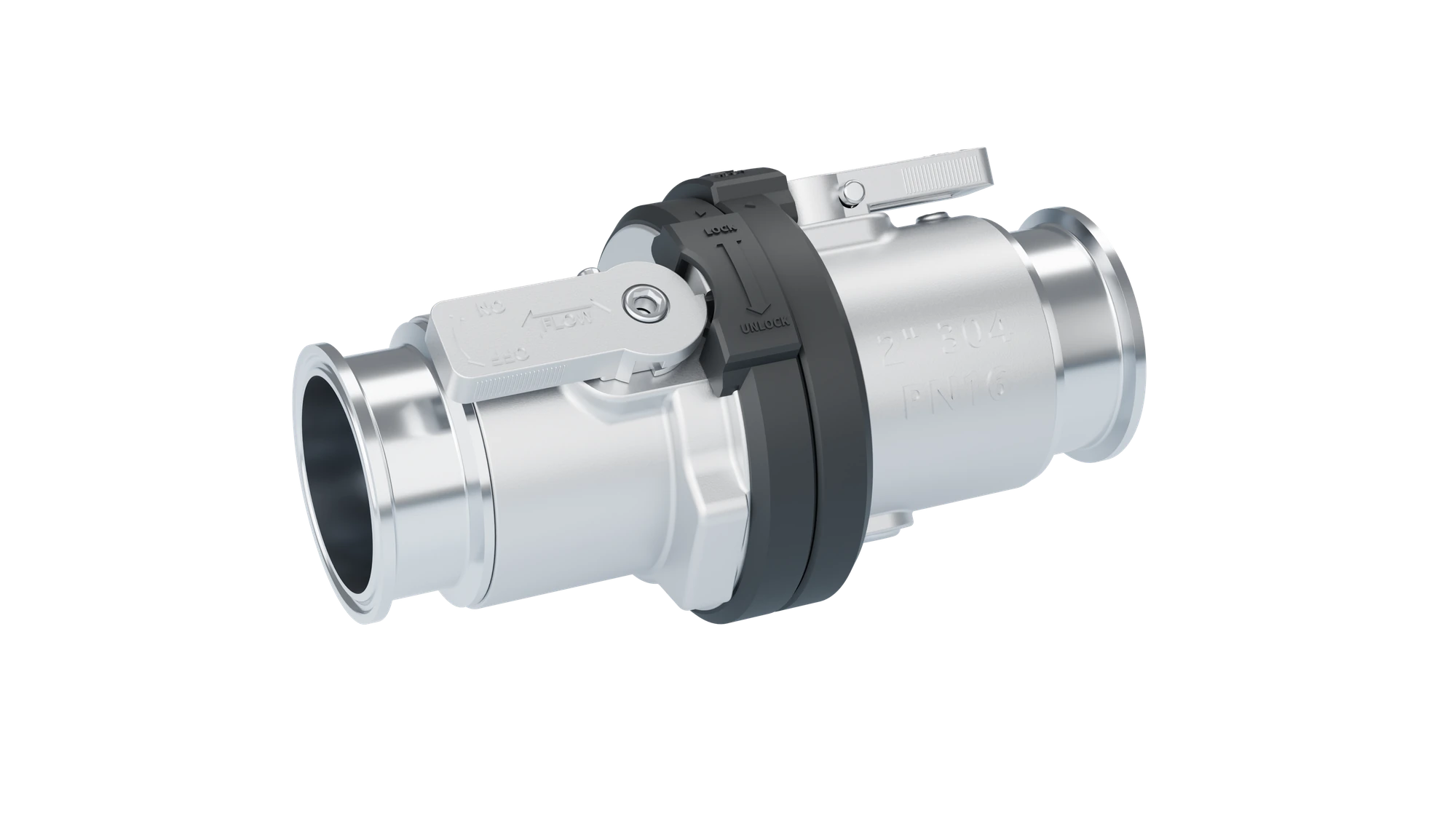
FULL-FLOW CONNECTION · SEQUENCED INTERLOCK
Values are subject to the approved configuration. Product visuals are illustrative.
01 / SYSTEM THINKING
More than components. A connected service strategy.
Start at the service point. Coordinate the valve, hose, retention hardware and mating interface.
02 / THE NP83 PLATFORM
Make the service sequence visible.
From docking to separation, each step has a defined operating state.

A CONTROLLED SERVICE SEQUENCE
Align & couple
With both valves closed, dock the coupling, rotate to its coupling stop and check the alignment marks.
Appearance and sequence illustration. Follow the instructions for the supplied configuration.
Mechanical interlock does not replace system depressurization, fluid management or safe operating procedures.
View the NP83 technical overview03 / CONNECTION PORTFOLIO
A complete connection path.
Match each service point with the appropriate connection family.
01NP83
Dry-Break Interlock Valve
A controlled sequence for coupling, opening, closing and disconnecting.
Explore product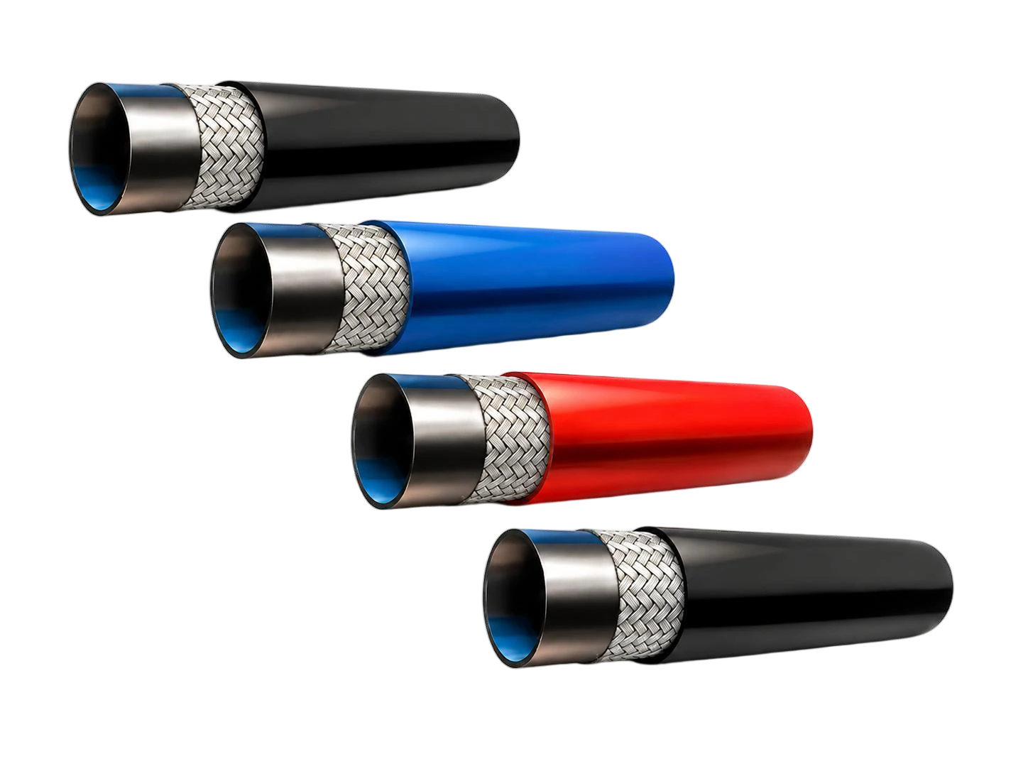 02
NLH · EPDM
EPDM Liquid Cooling Hose
Flexible coolant routing, specified around the fluid, bend space and end assembly.
Explore product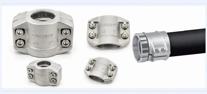 03
NPRK · STAINLESS
Stainless Steel Safety Clamps
Select by measured hose OD and review the hose, clamp and fitting as an assembly.
Explore product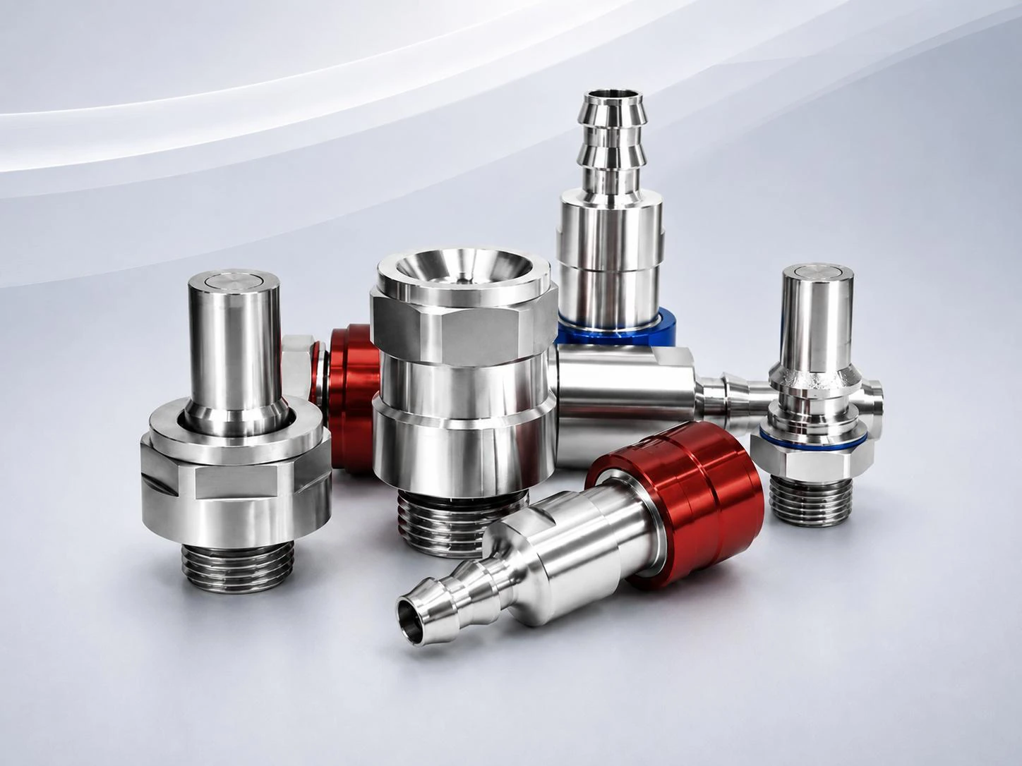 04
UQD / UQDB
Liquid Cooling Quick Disconnects
Push-to-connect interfaces for rack and equipment service, reviewed by size and duty.
Explore product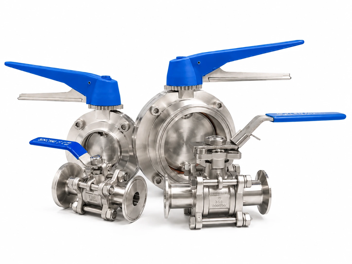 05
SANITARY VALVES
Sanitary Butterfly & Ball Valves
Sanitary isolation with multiple end connections and actuation configurations.
Explore product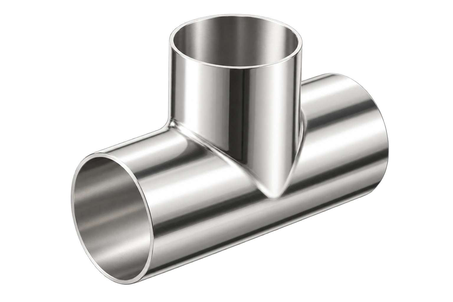 06
SANITARY FITTINGS
Sanitary Fittings & Custom Interfaces
Elbows, tees, reducers and adapters that connect standard components to real systems.
Explore productStandard and custom components, selected around one application brief.
Open the selection workspace04 / APPLICATION CONTEXT
Understand the system. Then define the connection.
Every connection location has its own installation, service and routing requirements.
Facility & CDU side
Define isolation and service requirements around the primary loop, including duty, mating interface and access.
Share your system requirements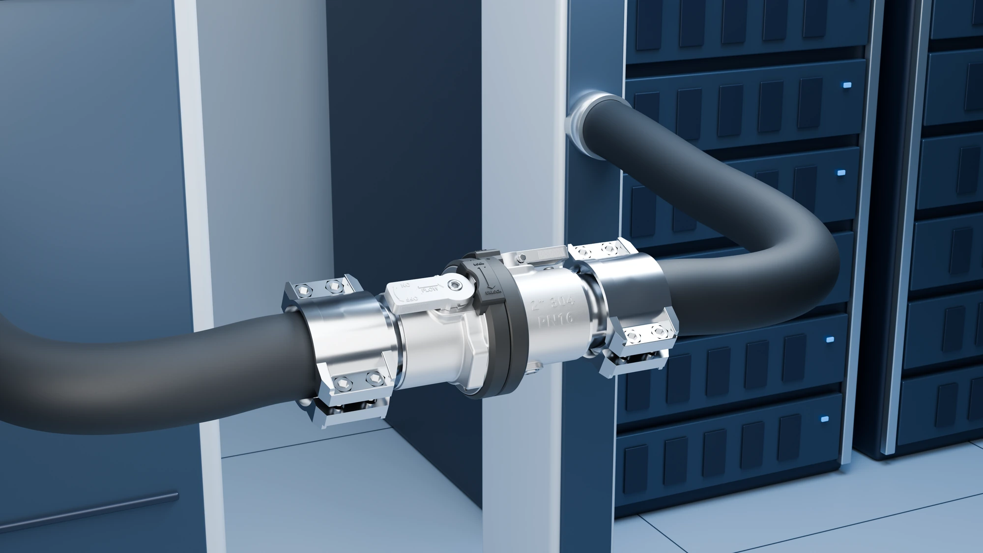
06 / ENGINEERING RESOURCES
Bring the conversation onto the same page.
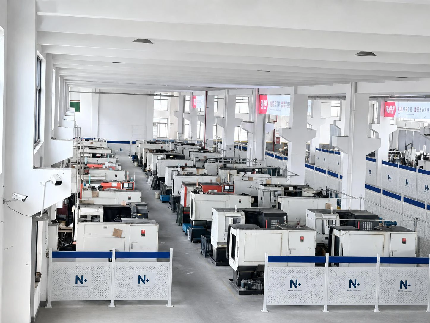
The latest company brochure brings products, manufacturing and selection into one reference.
COOLING
CONNECTIONSNP83 / CONNECTION TECHNOLOGIES
PDF / 24 PAGES
Liquid Cooling Connection Systems · English
Company, product, manufacturing and engineering overview for international teams.
Open brochure系统NP83 / CONNECTION TECHNOLOGIES
PDF / 24 PAGES
Liquid Cooling Connection Systems · Bilingual
Chinese-led bilingual edition for cross-team technical discussions.
Open brochureLET’S DEFINE YOUR CONNECTION
From a drawing to a defined connection.
Tell us the fluid, pressure, temperature and interface. Start the engineering conversation with a clear brief.
Start an application review