Full-flow path
A ball-valve flow path for the main connection. Review flow and pressure drop for the selected configuration.

NP83 / FLAGSHIP PLATFORM
FULL-FLOW CONNECTION. DEFINED SERVICE SEQUENCE.
A defined relationship between valve position and coupling action. Built for controlled isolation, service and replacement within liquid cooling circuits.
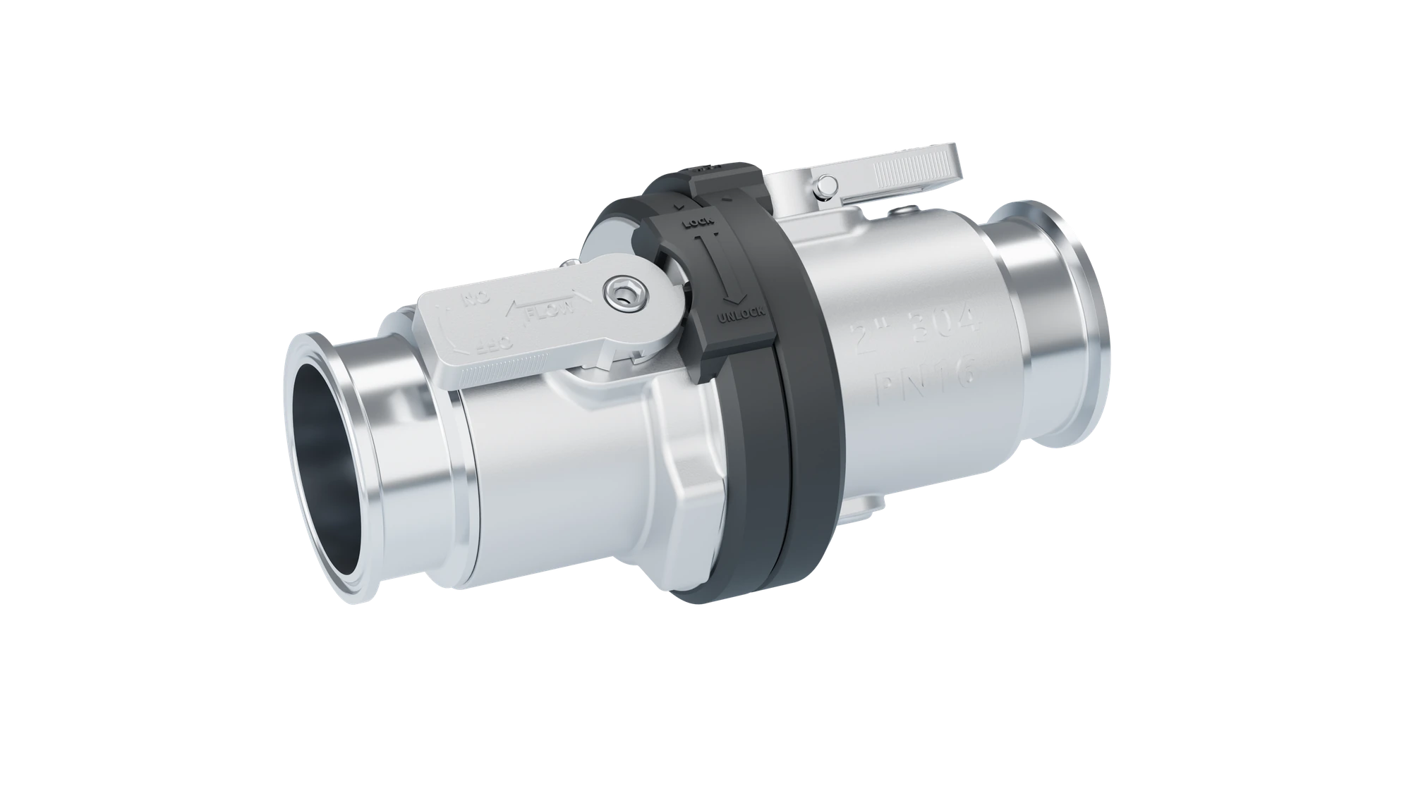
A ball-valve flow path for the main connection. Review flow and pressure drop for the selected configuration.
Valve position and separation are mechanically related to establish a defined operating sequence.
Clamp, threaded, hose-barb and project-specific ends are confirmed against drawings.
01 / OPERATION
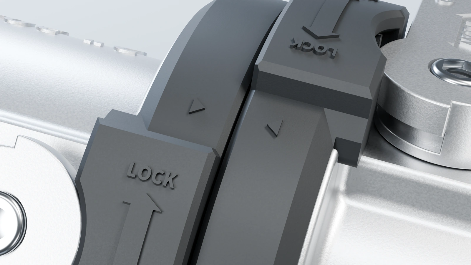
A CONTROLLED SERVICE SEQUENCE
With both valves closed, dock the coupling, rotate to its coupling stop and check the alignment marks.
Appearance and sequence illustration. Follow the instructions for the supplied configuration.
Follow system isolation and pressure-management procedures for the actual fluid and residual pressure. The interlock is not a substitute for system safety procedures.
02 / REFERENCE CONFIGURATION
Reference configurations for initial selection; approved drawings and the order define the final specification.
| Selection item | Reference configuration |
|---|---|
| Working pressure | 16 bar / 232 psi |
| Assessment pressure reference | 24 bar / 348 psi |
| Temperature range | −20 to +80 °C / −4 to +176 °F |
| Reference nominal sizes | NPS 1, 2, 3 (1″, 2″, 3″) |
| Body and ferrule reference material | 316L stainless steel |
| Linkage reference material | 304 stainless steel |
| Seal material reference | EPDM / PTFE |
| End configurations | Clamp / Thread / Hose barb / Custom |
03 / END CONNECTIONS
Confirm the mating interface before defining seals and assembly.
01 / CLAMP
Confirm the ferrule standard, dimensions, seal profile and clamp combination.
02 / THREAD
Specify the thread standard, size, male/female orientation and sealing method.
03 / HOSE & CUSTOM
Review hose ID/OD, clamp, engagement and installation envelope together.
NP83 / APPLICATION ENGINEERING
Define the connection task before confirming the assembly. Select what you know and carry the brief into your engineering inquiry; unresolved items can be discussed with our team.
04 / ENGINEERING QUESTIONS
Select by service location, bore, available space and operating requirements. Different families are not automatically interchangeable.
No. Images illustrate appearance. Approved drawings and the order configuration define materials, seals and markings.
Provide fluid and concentration, pressure and temperature, flow, bore, mating drawing, service procedure and required inspection documentation.
This page does not state unverified quantitative guarantees. Define the required tests and acceptance criteria for the target configuration, then confirm available records.
LET’S DEFINE YOUR CONNECTION
Tell us the fluid, pressure, temperature and interface. Start the engineering conversation with a clear brief.
Start an application review